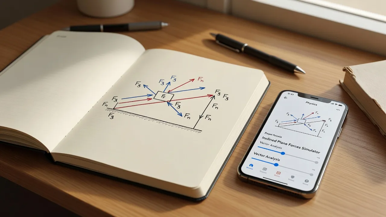
A free body diagram (FBD) is a graphic vector representation used in physics to visualize all external forces acting upon an isolated system. Drawing one correctly takes under five minutes once you master isolating the object, identifying long-range and contact forces, and setting a coordinate axis. If you ever feel like physics is hard, mastering this single visual technique will solve roughly 80% of introductory mechanics problem roadblocks.
As of September 2026, physics curricula have shifted away from older, informal sketch models toward strict vector-arrow standards required on standard exams. If you need a fast check while studying at home, tools like ThinkAssist let you snap a photo of your hand-drawn diagram to verify vector directions and net force calculations.
The table below outlines the five steps to construct a precise diagram.
| Step | Core Action | Realistic Time | Tools & Concepts Needed |
|---|---|---|---|
| 1. Isolate the Object | Replace the object with a single central dot or simplified box | 30 seconds | Pencil, paper, system boundary concept |
| 2. Add Field Forces | Draw non-contact forces acting from the center of mass | 30 seconds | Gravitational weight equation ($F_g = mg$) |
| 3. Add Contact Forces | Draw vector arrows everywhere physical touching occurs | 90 seconds | Normal force, friction, tension, drag |
| 4. Set Coordinates | Align x- and y-axes with the direction of acceleration | 30 seconds | Custom tilted axes, vector decomposition |
| 5. Write Force Equations | Sum vectors into algebraic equations along each axis | 120 seconds | Newton's Second Law ($\Sigma F = ma$) |
Step 1: Isolate the target object as a single point or simplified shape
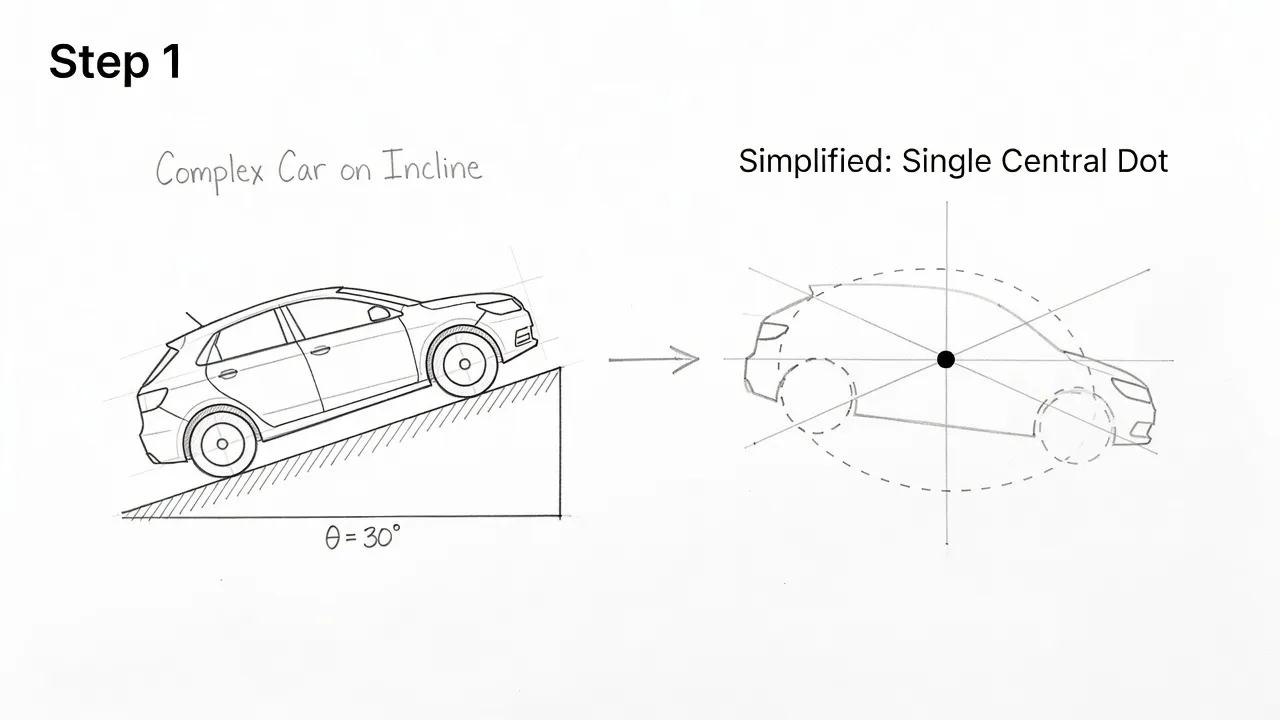
To isolate the system, remove all surrounding background elements and represent the primary object as a simple square or central dot mass. Do not draw trees, ramps, ropes, or person figures in your final diagram.
Older textbook guidelines from past decades often encouraged drawing realistic objects, but modern grading standards penalize decorative clutter. Converting an object into a single point mass prevents you from misplacing the origin point of your vector arrows.
If a problem involves multiple connected objects, draw a completely separate diagram for each object. Isolating each component independently is necessary before you can link them together through Newton's third law.
Step 2: Draw non-contact field forces starting with gravity
Non-contact field forces act across a distance without physical touching, starting with the gravitational weight vector pointing straight down toward the center of Earth. Label this vector as $F_g$ or $W$, with its arrow origin anchored directly on your central dot.
Unless you are working on advanced electromagnetism problems, gravity is usually the only field force you need to include in basic classical mechanics. The magnitude of this vector is calculated using the formula $F_g = mg$, where $m$ is mass and $g$ is local gravitational acceleration.
Understanding how to compute the exact scalar size of this arrow requires a firm grasp of magnitude in physics. Always draw field force arrows pointing away from the central mass point in the direction the force pulls.
Step 3: Identify contact forces along every physical boundary
Contact forces occur everywhere another physical object touches your isolated item, generating normal forces, friction, tension, or applied pushes. Trace your finger around the perimeter of the physical object in the original problem statement to catch every contact point.
For every surface touching your object, draw a normal force vector ($F_N$) pointing perpendicular to and away from that surface. If the surface has roughness and the object moves or attempts to move, draw a friction force vector ($F_f$) pointing parallel to the surface, opposing motion.
Outdated static diagrams frequently treated the normal force as automatically equal to gravitational weight. Modern physics courses penalize this assumption because normal force changes when objects sit on inclined ramps or experience angled pulls.
Step 4: Establish a custom coordinate system aligned with acceleration
Set up your x- and y-axes so that one axis aligns directly with the direction of actual or expected acceleration. For objects on a flat floor, standard horizontal x-axes and vertical y-axes work best.
When dealing with inclined planes, rotate your coordinate frame so the x-axis runs parallel to the ramp surface. Rotated axes keep your acceleration along a single variable axis, preventing messy simultaneous vector equations later.
Standard Axis (Flat Surface):
       +y
        |
   -x --+-- +x
        |
       -y

Tilted Axis (Incline Plane):
         +y
        /
   -x --+-- +x  (Parallel to ramp surface)
      /
    -y
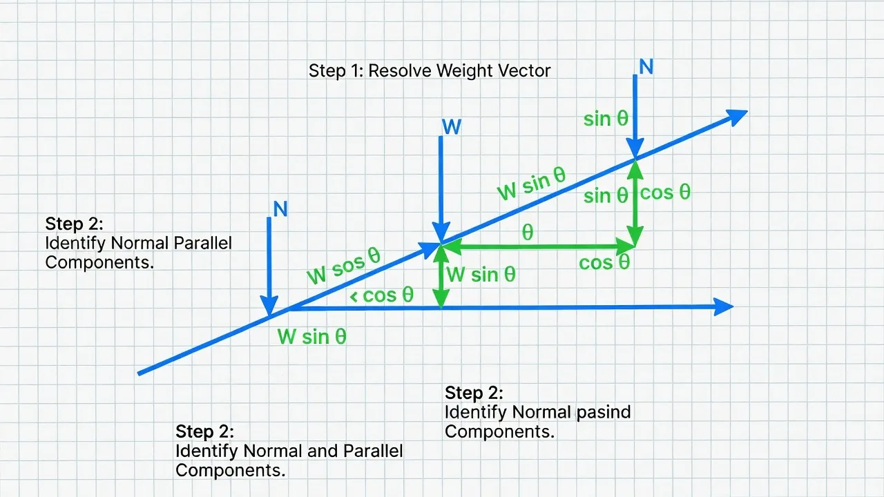
Once your axes are set, break any force vectors that sit at an angle between axes into their trigonometric components ($F\cos\theta$ and $F\sin\theta$). Drawing vector components as dashed lines helps separate them from true primary forces.
Step 5: Label vectors with standard notation and write Newton's second law equations
Label every arrow with explicit force notation ($F_g, F_N, F_f, F_T$) and set the sum of forces in each direction equal to mass times acceleration ($\Sigma F = ma$). Vector arrow lengths should roughly reflect their relative magnitudes so balanced forces look visually equal.
Write out two algebraic force summary equations: one for the x-axis ($\Sigma F_x = ma_x$) and one for the y-axis ($\Sigma F_y = ma_y$). If the object remains stationary or moves at a constant velocity, set acceleration to zero ($\Sigma F = 0$).
Practicing this step is essential when preparing for exam questions like those found in an AP Physics 1 FRQ study guide. Once your equations are written down, you can solve for unknown variables like acceleration, tension, or coefficient of friction.
How does The Physics Classroom teach drawing free-body diagrams?
The Physics Classroom teaches free-body diagrams using a four-step type-classification method paired with interactive practice modules. Their approach focuses on identifying the physical situation first before assigning individual force vectors.
Their curriculum breaks force identification into simple physical categories:
- Identify gravity ($F_{grav}$) pointing straight down.
- Check for surface contact to add normal force ($F_{norm}$).
- Look for ropes, cables, or wires to add tension ($F_{tens}$).
- Evaluate surface sliding or air resistance to add friction ($F_{frict}$) or drag ($F_{air}$).
Their site offers built-in diagnostic tools that let you build diagrams interactively on screen. This structured method helps beginners avoid adding fake forces like "inertia" or "velocity arrows" that do not belong on an FBD.
How does Khan Academy teach free body diagrams?
Khan Academy teaches free-body diagrams through video walkthroughs that emphasize breaking diagonal vectors into perpendicular x and y components. Their lessons highlight how forces balance out during equilibrium states versus non-zero acceleration states.
Sal Khan introduces diagrams by drawing vector arrows with proportional lengths directly from a central mass dot. The platform uses interactive exercise sets that ask you to select correct force directions for tricky scenarios, such as elevators accelerating upward or blocks sliding down friction-filled ramps.
Khan Academy places heavy focus on vector addition principles. They demonstrate how tail-to-head vector summation relates directly to the net force vector acting on the system.
How does HyperPhysics explain free-body diagrams?
HyperPhysics explains free-body diagrams through concept maps that link force vectors directly to fundamental mechanical principles and interactive calculation trees. Hosted by Georgia State University, the platform provides a graphical node network connecting force concepts.
The HyperPhysics model focuses on system boundary separation:
- Isolate the specific mass from its environment.
- Replace all external contact surfaces with equivalent vector forces.
- Apply Newton's laws of motion to solve the resulting simultaneous equations.
Their site provides JavaScript calculators where you can input force magnitudes to see resulting vector shifts in real time. This functional layout makes it an effective reference for verifying mathematical results in homework problems.
What free body diagram activities does PhET offer?
PhET Interactive Simulations offers dynamic HTML5 visualizers like "Forces and Motion: Basics" that allow students to adjust friction, mass, and applied forces in real time. These simulations show force vectors growing, shrinking, and canceling out live on screen as motion changes.
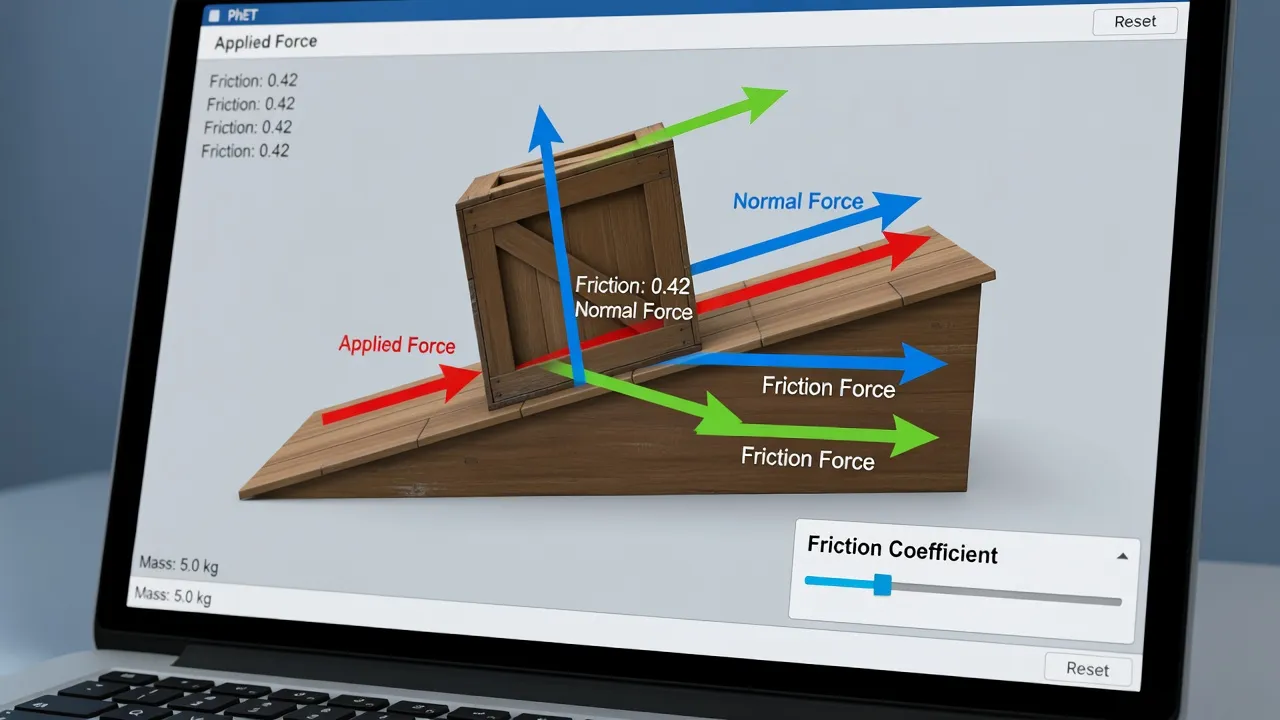
Students can toggle visual overlays to see total net force vectors alongside individual contact vectors. Watching vector arrows change live builds intuition for how applied pushes interact with static and kinetic friction limits.
PhET simulations also offer active graph tracking for position, velocity, and acceleration alongside force vectors. Seeing these metrics change together clarifies why constant velocity means net force must equal zero.
What does MIT OpenCourseWare cover on free body diagrams?
MIT OpenCourseWare covers free-body diagrams within its Classical Mechanics curriculum, focusing heavily on rigid body dynamics and complex multiparticle constraints. Their 8.01SC course treats FBDs as the primary tool for translating physical systems into differential equations.
MIT's instructional material goes beyond simple point-mass representations:
- Rigid Body Mechanics: Drawing force vectors at specific line-of-action contact points to evaluate torque.
- Multi-body Constraints: Setting up paired systems linked by massless pulleys and cables.
- Non-inertial Frames: Managing fictitious forces like centrifugal force in rotating reference frames.
Their lecture notes and problem sets challenge students to apply diagrams to multi-axis rotational systems. Mastering these advanced diagrams is standard preparation for university-level engineering physics exams.
What free body diagram teaching resources does AAPT provide?
The AAPT provides peer-reviewed lesson plans, Physics Instructional Resource Association (PIRA) demonstrations, and research-backed diagnostics like the Force Concept Inventory. These resources help educators fix common student misunderstandings regarding vector drawing.
Physics education research published by AAPT shows that students often make specific errors:
- Drawing velocity arrows as if they were force vectors.
- Inventing an "outward force" on objects moving in circular paths.
- Forgetting that normal forces disappear when an object loses surface contact.
AAPT resources provide teachers with targeted worksheet sets designed to break these common habits. Using active-learning physics tutorials ensures students build clear vector diagrams based on real interaction laws rather than guesswork.
How to verify complex free body diagrams with AI
You can check your free body diagrams instantly by snapping a picture with an AI problem solver to confirm your force direction and equation setup. Checking your work manually can be slow when managing inclined ramps, tension cables, and friction values at once.
Using the ThinkAssist app allows you to snap a picture of your handwritten diagram or physics problem statement. The app uses automatic subject detection to analyze your vector layout, identify missing forces, and show step-by-step mathematical solutions.
ThinkAssist Verify
Your handwritten free body diagram is analyzed as follows:
- Image captured: Block sliding down 30-degree incline
- Subject detected: Classical Mechanics / Vector Forces
- Vector check:
- Weight (Fg): Correct (straight down)
- Normal (FN): Correct (perpendicular to ramp)
- Friction (Ff): Missing! Should point up-ramp
- Step-by-step solution generated
Having a 24/7 tutor tool available means you never get stuck guessing whether your normal force vector is pointed correctly. It saves past explanations automatically, making it easy to review solved diagrams when studying for upcoming tests.
Common free body diagram mistakes to avoid
The most common free body diagram mistake is adding fake forces that do not originate from a physical interaction, such as centripetal force or motion forces. Centripetal force is the net total of real forces directed toward a turn center, not a separate arrow to add to your sketch.
Avoid these frequent vector drawing errors:
- Including Internal Forces: Only draw external forces acting on the isolated body, never forces the body exerts on other items.
- Misaligning Friction: Friction always acts parallel to the contact surface, directly opposing the direction of relative sliding.
- Drawing Velocity Vectors: Never put velocity or acceleration arrows directly on the free body diagram; draw them off to the side as reference arrows.
- Assuming $F_N = mg$: Normal force only equals weight on flat, non-accelerating horizontal surfaces with no angled applied forces.
Focusing on physical contact points prevents you from creating imaginary forces. Every arrow on your diagram must trace back to a physical surface touch or an established field force like gravity.
Frequently Asked Questions
What is the main purpose of a free body diagram in physics?
The main purpose of a free body diagram is to isolate a single body and visually represent all external forces acting upon it. This makes it easier to apply Newton's second law and set up correct mathematical equations to solve for acceleration or unknown forces.
Do you include velocity in a free body diagram?
No, you should never include velocity vectors on a free body diagram. Free body diagrams only display external force vectors acting on the object. If you want to show velocity, draw a separate arrow off to the side of your diagram to avoid confusing velocity with force.
How do you draw a free body diagram on an inclined plane?
To draw a free body diagram on an inclined plane, represent the object as a point mass, draw weight pointing straight down toward Earth, and draw normal force perpendicular to the ramp surface. Then rotate your x-axis parallel to the ramp and break the weight vector into perpendicular components using sine and cosine.
What is the difference between contact forces and field forces?
Contact forces require physical touching between objects, such as friction, normal force, tension, and applied pushes. Field forces act over a distance without physical contact, such as gravity, magnetic fields, and electrostatic attraction.
Is centripetal force drawn on a free body diagram?
No, centripetal force is not an independent physical force and should never be drawn as its own arrow on a free body diagram. Centripetal force is simply the net sum of real physical forces, like tension, friction, or gravity, pointing toward the center of a curved path.
How do you know which direction friction points on an FBD?
Friction always points parallel to the contact surface and opposite to the direction of relative motion or intended motion. If an object is sliding down a ramp, kinetic friction points up along the ramp surface.
Why is normal force not always equal to weight?
Normal force measures the push perpendicular to a supporting surface, which changes whenever surfaces are inclined or angled pushes are applied. On a ramp or an accelerating elevator, the surface does not support the full weight directly, making normal force different from gravitational weight.